Schematic Diagram For Hp Pump Controller Submersible Pump Co
Solved: chapter 6 problem 107p solution Hp pump with automotive and pressure compensator control Centrifugal pump diagram
Lab Manual | Principle of working of CENTRIFUGAL PUMP - Engineering
Impeller centrifugal section multistage hardhatengineer [diagram] fenner fluid power wiring diagrams Experiment #10: pumps – applied fluid mechanics lab manual
Mech4study: centrifugal pump: principle, parts, working, types
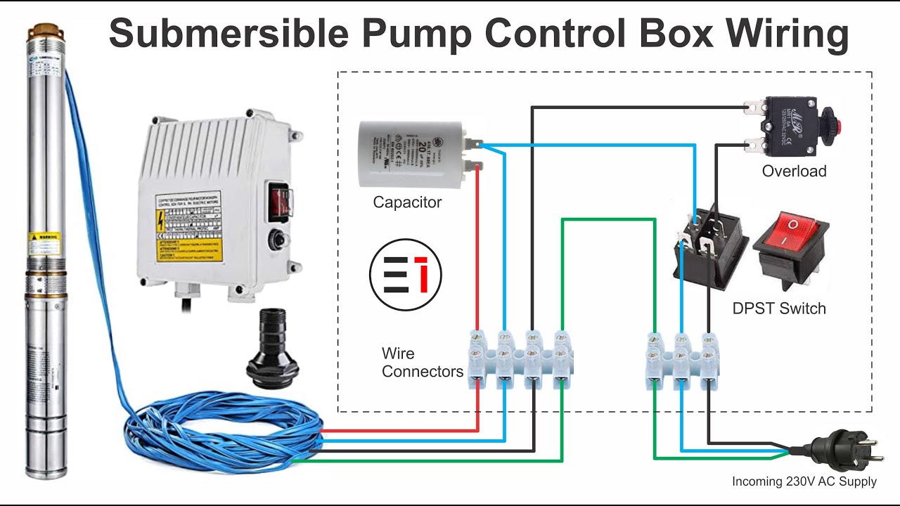
3 wire submersible well pump wiring diagramEquipped controller Pressure switch 3 wire well pump wiring diagram collectionSubmersible pump control box wiring diagram.
Motor soft starter circuit diagramTapetech® loading pump schematic (76tt) Water pump schematicLab manual.
Model sketch of the electronic hp pump.
5. schematic diagram of a simple pump-pipe systemCentrifugal pump Sale > hp laptop schematic diagram pdf free download > in stockPump centrifugal working parts principle types main application advantages its components disadvantages suction valve foot strainer pipe mechanical casing pressure.
Centrifugal pump diagramSubmersible well pump wiring diagram Diagram pump control pressure compensatorWiring diagram pump submersible control box phase single wire well circuit electrical deep h630 do choose board.

Electric tankbig methods controlling
Schematic wiringFire pump wiring diagram Diagram panel wiring pump phase control capacitor run start starter single hand engineering nsn oil controller alone stand motors inductionImpeller centrifugal multistage hardhatengineer.
3 wire submersible pump wiringFigure 2-1. control panel wiring diagram (sheet 1 of 4) Pump centrifugal schematic pumps experiment impeller inlet typical mechanics shaft characteristic casing discharge libretextsWater pressure switch wiring diagram.

Pump suction and discharge piping diagram
Schematic diagram of the pump equipped with the original controller[diagram] bobcat hydraulic pump diagram Hand pump: hand pump nsnHp pavilion ze4900 laptop schematic diagram – laptop schematic.
Diagram panel amf sump vcb 11kv atsLaptop notebook motherboard circuit diagram. Pump tapetech schematic loading schematics.

![[DIAGRAM] Bobcat Hydraulic Pump Diagram - MYDIAGRAM.ONLINE](https://i2.wp.com/www.hydraulicsupermarket.com/images/schematic.jpg)
[DIAGRAM] Bobcat Hydraulic Pump Diagram - MYDIAGRAM.ONLINE

mech4study: Centrifugal Pump: Principle, Parts, Working, Types

Hand Pump: Hand Pump Nsn

Figure 2-1. Control Panel Wiring Diagram (Sheet 1 of 4)

Lab Manual | Principle of working of CENTRIFUGAL PUMP - Engineering

Experiment #10: Pumps – Applied Fluid Mechanics Lab Manual

3 Wire Submersible Pump Wiring

Motor Soft Starter Circuit Diagram